First steps with ESP8266 wifi module
 Some weeks ago it was mentioned in hackaday.com a new wifi module was available at a very tempting price (I paid $10 for two ESP8266 units shipped). It is a full SoC system which firmware can be updated.
My main interest was to use it with Arduino projects and, perhaps, as a way to use my 3D printers wirelessly.
The module offers, among other choices (I2C, SPI) a serial connection, running at 115200bps. Getting it to work has been a bit weird, as documentation was not very accurate and I was not paying much attention either.
Care has to be taken with power supply as the unit is to be powered at 3.3V and using 5V will probably kill it. Likely it seems that I/O are 5V-tolerant (or so they seem till now).
My initial setup has been to use an Arduino UNO as a power supply for the 3.3V and another 3V USB to Serial adapter with one FTDI chip. This way I was able to interact with the board using a serial terminal software (Coolterm). Unfortunately my initial setup was a no go.
I initially connected GND, 3V3, TX and RX pins. I was lucky a friend of mine did the same dance before and figured out that at least an additional pin needs to be HIGH too, which is CH_PD pin that acts as an enable signal, without it the board is mute and deaf.
Once you connect this last pin to VCC (remember 3.3V) the module is brought to life, and after some garbage in the serial port you can read the word "ready". Once you get there things will start to get interesting.
I have found the best was to interact with the module is using an Arduino with at least two serial ports. Whether you use a Leonardo or a Mega, you can get an extra hardware port to communicate with the module and the other for interacting with the user via the serial terminal.
You can do the basic stuff if you load the Blink example on your Arduino UNO (so you are positive Arduino serial port is not used) and you connect the TX and RX pins of the module to pins 1 and 0 of Arduino. But this setup is only for you to use Arduino's IDE Serial Terminal function.
If you want to start coding for Arduino to do some useful stuff you need to be able to both reprogram the Arduino (which you cannot with the previous setup) plus accesss to or being accessed from the Internet, a second serial port is needed. One that can work at 115200bps. Unfortunately SoftwareSerial can only work up to 19200bps, so it is out of the question.
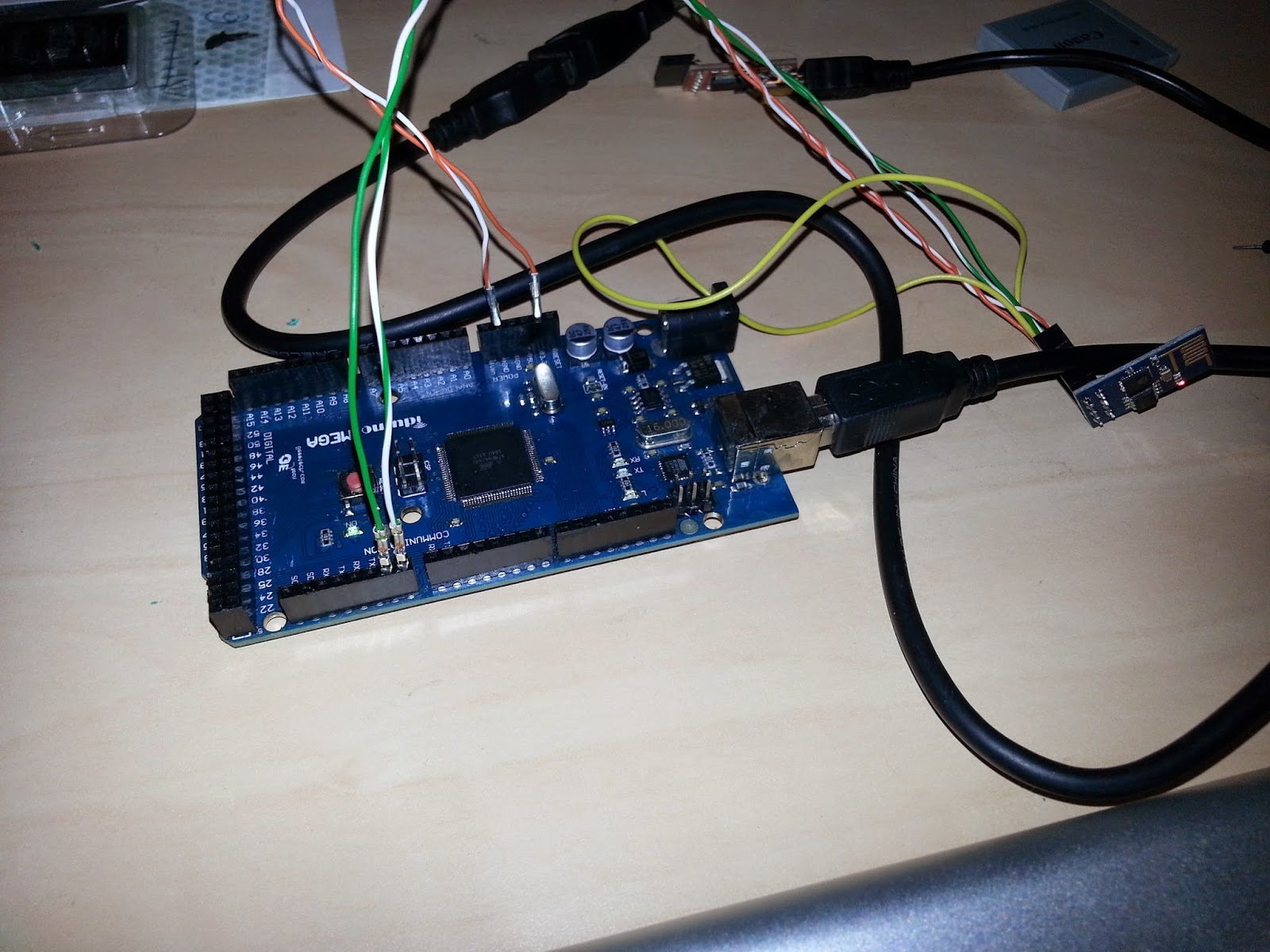
The picture above shows how I am using Serial3 on Arduino Mega as the communication channel with the module, while Serial is kept for the user interface (with the serial monitor of Arduino IDE).
I have created a simple bridging code between the two ports as you can see below:
// simple terminal on Serial3 <--> Serial for Arduino Mega void setup() {
Serial3.begin(115200);
Serial.begin(115200);
}
// copy from and to each port void loop() { while(Serial3.available()) Serial.write(Serial3.read()); while(Serial.available()) Serial3.write(Serial.read()); }
Basic commands
Once you get your module to answer your commands, you may want to try AT+GMR to check which version is your firmware. Mine is 00160901.
You can reset the board with AT+RST command.
But the magic starts once you try AT+CWLAP command, that will provide you a list of available wifi access points in the area.
Next you want the board to join a certain access point (most of us want the board to act as a STA or wifi client that will connect to an access point). That behavior is selected with the AT+CWMODE=1. You will need to reset your board after making this selection.
To connect to your home/office access point you issue the command AT+CWJAP="yourSSID","yourWifiPassword"
The good news is that from now, every time you power the board it will try to connect to the same wifi network. You can see if it was successful by checking your router's DHCP client list. Alternatively you can check your module IP address with command AT+CIFSR. Once you know your board's IP address you can try pinging it from your computer. Do not be surprised if you get delays over 100ms sometimes.
If have made it so far, then your are ready for some fun uses.
TCP client and server modes
The module can handle up to four connections at a time. The card can be set to allow connections with the command AT+CIPMUX=1
A TCP connection can be started, for example to a web server by AT+CIPSTART=0,"TCP","www.yourwebsite.com",80
Once you get the OK response, you should get the text "Linked" next showing you the connection has been established.
Now it is when things get a bit odd. Whatever you send to the serial connection of the module IS NOT transmitted through this new connection but just interpreted as new commands by the module board. If you want to transmit something you need to use the command AT+CIPSEND=0,50 to send in this example 50 bytes (change the number by one of your choice). After this command you get a prompt ">" so you can type your 50 character that will be transmitted through the TCP connection you just created.
If at any time data is received through any open connection, it will be signaled by a line of text over the serial interface "+IPD,0,1024:....". Number 0 is the identifier of the connection data is coming from. 1024 is the number of bytes that come afterward, not including the colon that acts as a marker. Next all the 1024 bytes will appear over the serial line.
If you receive several TCP segments, each one of the them will be signaled as the one above, stating the correct number of bytes of each one.
The TCP connection is meanwhile kept open. If you want to close it at any time, use the command AT+CIPCLOSE=0 (0 is the connection id number, that may change in your case). No matter who closes the connection, once the connection is closed you will get a line with the message "Unlink" warning you about a connection being closed.
You can check the status of your connections with command AT+CIPSTATUS
The board can also enable a local TCP server with command AT+CIPSERVER=0,8888 (where 0 is the connection id and 8888 is the port number). Once created, you can connect from your computer using telnet or netcat to your board's port 8888. Again any data the board receives from the connection will be announced with the +IPD,0,bytes header. And you can send data to the client with AT+CIPSEND command as you did when using the TCP client connection.
Contrary to the documentation, I could not make any connection if AT+CIPMUX=0. That is supposed to allow only one connection but it did allow any in my case.
Multiple connections to the TCP server are possible (I guess up to four, but I have not tested it).
Power supply issues
Sometimes I have got the board die on me with a message that suggested a watchdog timer reseted the board due to a malfunction. This seemed to happen a lot while using the board at the office (clone computer) but it did stop happening when trying the board at home with an old-ish iMac. My guess is that the Arduino UNO and or my office's computer USB max current was quite close the peak current needed by the board. However, with the Mega connected to the iMac I have not seed the message all evening.
To be on the safe side, get yourself a 3.3volt power supply that can provide up to 400mA and you will be ok. Along the ride, there have been moments when the board did not answer me right away for reasons unknown, for example not responding for a while to AT+CWLAP command (for listing access points).
I know there are more modern versions of the firmware and the newer ones do include a way for the board to self upgrade once it get online (cloud upgrade) which is kind of cool. Once I learn whether it is worth or not I might upgrade.
Not exactly what I expected
Unfortunately, using the board with a 3D printer running Marlin software on an Arduino Mega will require some filtering of the data sent back an forth. As received data is prepended by the text "+IPD,id,bytes:" and in order to send data you have to invoke command "AT+CIPSEND=..". All this makes the communication not very transparent, at least not as transparent as when you use a Bluetooth module. But it is still doable with some coding.
Finally, what I did not like either is the link throughput that was below 80kbps in my tests, where the module is not in the same room as the wifi router.
However, for data logging on the cloud or IoT projects based on Arduino I think this board is a great tool as it allows IoT integration at a very affordable price.


Comments
Te cuento estoy intentando hace un par de dias hacer funcionar el ESP8266, sin exito.
Lo conecto a mi Arduino Uno en los pines de 3.3v, gnd, tx1, rx0. Previamtente cargo el sketch de blink y voy al monitor serial a ver que pasa. Nada de nada....
mando un comando AT+RST y se prende el led azul, pero nada pasa en mi monitor.
Si conecto, el CH_PD a 3.3v del arduino, este se cuelga el sketch y tengo que desconectar.
No estoy usando ningun tipo de shifter ni divisor para bajar el voltaje del tx y rx (lei por ahi que es tolerante a los 5v)
Tambien lei que el consumo del ESP8266 es mayor al que Arduino uno pude ofrecer. ¿ sera eso?. ¿Tenes algun consejo para ofrecerme?. Desde ya muchas gracias.