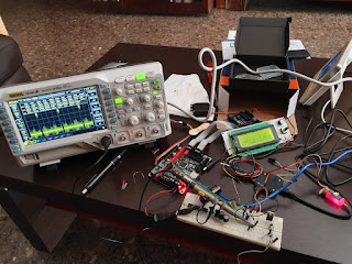
Testing SKR 1.3 board with Marlin 2.0.x
Not that I really need it but given the price I had to buy one of these units just to get a feel of it. At less than $20 it was a steal. And most of what I have seen from the board is to be liked. But, as usual, it took me a large amount of time to get everything working, as a few hurdles prevented me to succeed on the first try.

Luckily, there is a huge Marlin community and getting the software up and running was easy-peasy, once you have Atom/PlaftormIO installed (which I did). So the basic configuration is well covered on the net. The board can be powered either from the DC input (12/24V) or from the USB (jumper-selectable).
But ... expect trouble if you are powering it from USB and attempt to configure TMC2208 UART mode. It will not work until you power the board with DC too. And it will only work if you have properly configured your firmware and set the right driver solder blob so UART is connected to pin number 4 of the driver carrier board and you have set the proper solder blob on the TMC2208 board. If not, you will get the dreaded "TMC CONNECTION ERROR" message on your LCD or an error when reading driver status using M122 g-code command.
But what made me waste a significant amount of time was the BLTouch support. Let me first tell you there is nothing wrong about it (possibly) but my BLTouch was, on closer inspection, not the original from ANTCLABS but a similar-looking one "based" on it. This unit was completely unresponsive to any BLTouch command but, if I connected a regular servo instead, it will react properly to the different commands, so the SKR 1.3 was doing its job properly.

I ended up deploying a considerable amount of effort until I got it to work. The first thing was to try the probe with a single Arduino and check whether it will react to the different servo commands (which it did at the first attempt). So the probe while not the original actually worked as expected. So then, what was wrong with the SKR 1.3 output? According to my servo, that output was working ok too.
So I assumed that either the output was 3.3v instead of 5v logic and that was causing the problem or maybe it was not powerful enough. But the latter made not much sense as servo inputs are usually quite high impedance. But after a while, I concluded the signal input of this device is actually to blame, as it has a really low impedance (around 200 ohms) that would require a significant amount of current to work properly (something Arduino had no trouble doing but the SKR board failed to provide). Again, not an SKR board fail.

The circuit above did the trick to make it work after just a regular CMOS buffer failed to provide enough current for that dreaded probe to work. I used BC338 NPN transistors but I guess any small signal NPN should work. My guess is that input has a really low pull-up resistor, maybe due to an error in the cloning of the original design (just a guess). Users combining that probe with an AVR-based board most like experience no trouble but for me, it was quite a search, as I had to discard many other possibilities, plus the fact my 24V supply was quite noisy did not help either.


Comments
Many thanks
Javier
Regards
Javier