Making sense of toolpaths

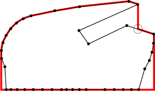
On my CAM project I am using the intersection of a part with a given plane to determine later the proper tool-path for three-axis machining. But sometimes, parts are such that the intersection line contains some concavity. So I detect whenever the tool cannot reach that line and create a suitable solution. In the picture the red line in the top removes any concavity as seen from Z-axis top, converting that polyline into another that might be machined from the top. It is interesting to note that one extra point needed to be created and appears marked with a dashed circle, though strictly speaking both bottom corners of the red line are new points too, but they are not over any of the original polyline space. A second problem appeared once I obtained not one polyline but several of them as a result of objects that contain holes or several domains with respect to the cutting plane as it is shown in the image below. In this other case, the different polylines need to ...
