Posts

Just add a shutdown button, it will be easy, they said ...

Image
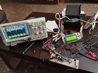
Finally, one of our Art projects is selling. My partner asked me to add a power-down button so the museum personnel has an easy way to power off the installation. Adding that to a Raspberry Pi cannot be very difficult using one of the GPIO pins or so I thought. So the first iteration was something like this: a small Python program that will detect a falling edge on an input GPIO input. Tests worked ok, I was using the internal pull-up resistor and a normally-open switch would connect the input to ground. Once the falling edge was detected a detailed shutdown sequence would be initiated (to avoid any damage a heated element would need to be retracted by a servo). As usual, things worked well in theory and in the lab, but failed miserably in the real test. So I thought that, perhaps, the wiring was too long and close to a power line and that might be picking up some noise, that eventually triggered an unwanted shutdown (sometimes even before the system started working ;-) So the...
Testing SKR 1.3 board with Marlin 2.0.x

Image
Not that I really need it but given the price I had to buy one of these units just to get a feel of it. At less than $20 it was a steal. And most of what I have seen from the board is to be liked. But, as usual, it took me a large amount of time to get everything working, as a few hurdles prevented me to succeed on the first try. Luckily, there is a huge Marlin community and getting the software up and running was easy-peasy, once you have Atom/PlaftormIO installed (which I did). So the basic configuration is well covered on the net. The board can be powered either from the DC input (12/24V) or from the USB (jumper-selectable).  But ... expect trouble if you are powering it from USB and attempt to configure TMC2208 UART mode. It will not work until you power the board with DC too. And it will only work if you have properly configured your firmware and set the right driver solder blob so UART is connected to pin number 4 of the driver carrier board and you have set the pro...

The art of compiling Meshlab and getting it running

I have been using Meshlab for quite a while as a powerful tool for automating 3D mesh calculations. Newer versions were not always more reliable than older ones, but mine was mostly a command-line usage more than interactive sessions so I got by. The latest stable release is still 2016.12 and it gets my work done (though some changes were made to the command-line switches that broke some of my scripts). I have been using it on 14.04, 16.04 Ubuntu systems and lately, I wanted to use it on the 18.04 Ubuntu. But for that version, I could not find a pre-compiled binary and the versión included with the distribution was Meshlab 1.3.3 that, you guessed it, uses a different set of command-line switches so it was not an option. Still, there was the choice to install a binary using the snap package system, which comes included in Ubuntu 18.04 and got me a working interactive Meshlab. But the meshlabserver command was nowhere to be found. It seems someone thought it best to rename it to me...

More on wireless uploading

Image
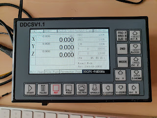
As usual, even best-laid plans face hardship, so now I can wireless upload g-code files to the USB memory connected to a DDCSV1.1 CNC controller. But, once I factor in not to upload a code line before I have got the remote echo of it, things get really slow. Like ten minutes per megabyte. Yes, I wanted it to be wireless. I could accept a not so fast upload speed, but 13 Kbps is not ok as we handle files in the 1-10 MByte range usually. A few seconds is ok, but half an hour or more is not. So I came up with yet another approach that would recycle some old-tech that I discarded years ago: There was a USB dongle that would accept an SD card and it would work as a USB pen driver but with a twist: the unit did also have wifi connectivity. So the users could access the content of the SD card wirelessly as a network disk. That was cool and made totally unnecessary (apparently) my previous work but, there was a catch: The device would work either as a pen drive (as soon as you connect it ...

Enabling wireless uploading of jobs to a stand-alone CNC controller

Image
I explained a while ago how I set up a farm of CNC routers. At that time a combination of an Android tablet and an Arduino running Marlin was a good compromise for a DIY system. Over the years, one thing that was demanded was to have controllers that are a single machine (as the USB cable from the tablet to the Arduino creates problems at times due to machine's vibration). Several options are available in the marketplace of small and affordable CNC controllers that require no computer and can run jobs off a USB pen drive. No computer or tablet required. One of such a system, running Linux, with a nice display and keyboard, is the Digital Dreams units DDCSV1.1 and above. I bought one unit a couple of years ago but it was never used, but now I am giving it a try on a test machine, where we want to reach 5000 mm/s^2 accelerations and speeds above 30 meters per minute and the fact that unit could create step pulses at a 500kHz rate really caught my attention. It can do that n...

A simple plan

Image
One of the things I did not like about a new printer was that the belt that moved the carriage was not laying parallel to the axis of motion (left) but at an angle, as shown in the picture below (right): Such a belt path is not right as for each inch of motion in the axis a slightly different amount of belt is moved (the hypotenuse of a triangle instead of its long side). Most of the time, the angle is so small the difference is tiny. That is why the arrangement works and printers are printing even though they have this ugly hack. The problem is worse when the carriage is close to any of the two ends, as then one of the angles is not so small and that creates a bigger error. But the question is: how big the error can be? Well, it took me a good part of a weekend to figure that out, among other things because wxMaxima does not like to calculate the intersection of two circles easily . So the first thing I needed was to model the anomalous belt path in a geometric model I co...

Anycubic Chiron 3D printer

Image
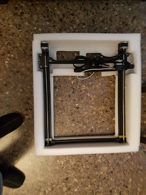
Some of my ongoing projects required a larger 3D printer and I saw a good deal on a printer that had good reviews (except for its weird bed leveling system) so I bought one off Anycubic's Aliexpress shop shipped from Germany. I got in in less than a week and putting it together took me a bit more than one hour. It is basically two parts, shipped flat, that you place at a square angle to make a Prusa i3 like configuration. The printer comes with all the tools you need, including the wire cutter to use to remove the zip ties that keep the bed from moving while in transit. The 400x400 mm bed features glass on top with a special texture that does what it promises: good adhesion while hot and easy release of parts when cold. These two brackets will reinforce the vertical axis beams fixed to the horizontal extrusions. Once built, the manual called for a manual or automatic bed leveling. That I did not like as it seems the user has to decide which one is best. Someth...

Drawing from Inskcape using Bluetooth connection

Image
Some time ago I developed 4xiDraw , a 2D drawing machine using a single belt, a 3D printable clone of AxiDraw(tm) pen plotter. Instead of the EBB board they used, I opted for an Arduino-based solution, with a CNC shield and regular Pololu-like stepper motor drivers. Initially, I started using various Inkscape plug-ins that will convert the drawing into a G-code file. Once the G-code was created, I would use the UniversalGcodeSender program to stream it to the drawing machine. That worked ok, both wired and wirelessly (using Bluetooth). But later, a kind user named Torsten Martinsen migrated the existing AxiDraw plug-in to the 4xiDraw hardware controller. This way, plotting happened right inside Inkscape program without the need to messing with external files or other additional software. Very cool indeed! I left the project living its own life, with a lot of users creating their own version of it and doing all kinds of interesting hacks, till I received an awkward request fro...

Using Pynq with your Zynq

Image
I recently attended a one-day tutorial about Pynq by Xilinx. While it was on planet Earth I was not familiar with some of these names that sounded alien to me. But I was decided to get some update about the new FPGA offerings by Xilinx company. I am glad I did as I discovered a wide range of technologies I know nothing about that I reckon can be pretty useful. Unfortunately, becoming an expert on any of them will most likely require many hours of training. But I can share with you some of what I learned: Pynq is an open-source project by Xilinx to make it easier to use the programmable logic included in some of their SoCs. And that brings us to the second name I have never heard about: Zynq-7000 is a system-on-a-chip (SoC) by Xilinx that bundles an ARM microcontroller with a large FPGA.  In a nutshell, Pynq is a small Linux distribution that runs on a Zynq SoC with access to all the power of the embedded FPGA. But I guess the question here is what this can be useful for. Ri...

How to shutdown your interactive Art

Image
If you build a piece of interactive Art with an Arduino, there is not much harm you can cause it by just powering it down anytime. But when you use a computer, either a PC or a Raspberry Pi, bad things may happen if you just switch off the mains power unannounced. A common occurrence is that you are asked by the museum or exhibit managers for instructions on how to properly switch off your interactive Art installation. Experience shows us that the more difficult it is, the more likely one day will be done improperly. And I really hate when a piece that took a lot of effort to create goes to waste because of a problem triggered by a "rough" shutdown.  So one idea that has worked for us is to set up our system as a wireless access point. The person in charge of shutting the system down will use her phone to connect to our wireless network using a password we provided. Once connected just visiting a specific address and port number will cause the shutdown (first time th...

RPi3+ blues

Image
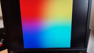
I have been working a few days improving an existing project based on a Raspberry Pi. It is a art piece with a vertical plotter that draws lines on with a pen. Software and data were already developed and I was just adding some finishing touches. I was given a new RPi3+ board to upgrade the system but when I connected the new board with the existing SD card the system did not boot up. As our system did not include an HDMI display but an embedded one, we did not have display unless the system could successfully boot. My first thought that then new board could be more power hungry than the existing one and therefore the existing power supply was not enough to keep up with the demand. I had to put back the older board and left the one for further testing. Once I managed to get an HDMI display connected to the board, I could see the image above. Not sure whether it was some Harry Potter add on the upper left corner or, maybe, someone trying to tell me there was something wrong with ...

New iPhone app too

Image
A few weeks ago I mentioned a new Android app was available to assist during the assembly of projects made of blocks of stacked layers of material. That will not be complete with a similar app for those of you own Apple cellphones and iPad tablets.  For the moment the app is available for iOS 12 devices . Supporting older versions has not been a priority as we did not want development to lag behind but we might venture there if we get enough requests.  As with the Android app, this version is free too. A sample model is embedded so you can see how it works (go to the gear menu).

Android app for block assembly

Image
Collaboration with a local company paved the way to the development of an Android app to represent 3D models that are built by joining a set of 3D blocks. Each block is made of a set of layers of parts machined by a 3-axis CNC machine out of foam sheets.  The manufacturing process is more or less outlined in this video: The problem here was for work workers to have an easy way to know the assembly of the parts without the need of having a computer screen. Given each one of them happens to have a smartphone that seemed the obvious choice. And that is the result (portrait video warning): As you can see in the video each block has a red number hovering it. And the low polygon count of the 3D mesh is just to ease on the amount of data transmitted and not a limitation of the program itself. I wanted to make this tool  useful for other users, so the file format is a regular ZIP file with .mim extension that contains three different elements: one binary STL file for each...

Speeding up nesting calculations

Image
Algorithms for free-form nesting has a cost that depends on the complexity of the polygons that represent the parts to be placed. The more complex (the more points) these polygons are, the longer the computing time. One might accept a slight waste of material if that can speed up the nesting significantly. The obvious idea is to simplify the polygons and for that task, there is a considerable amount of algorithms available. However, there is a bit of a catch in our case: If the simplification process renders a new polygon that is slightly smaller than the original one, this could be a problem as the actual part will not fit in the space allocated for it by the nesting software. The simplification performed by the red arrow creates a new polygon that, while it has fewer points, it cannot contain the original polygon inside and so it would be a bad idea to use the new for nesting purposes. On the other hand, the green arrow simplification does create a new polygon with fewer p...

Another stepper motor

Image
I was looking for a simple mock-up to be used to explain the operation of a stepper motor to my students. This is what I came up with: Just four coils on the edges of a plus-sign shape, where the two horizontal coils are connected in serial in a way that they create opposite polarity fields. Same arrangement for the two vertical coils. So we end up with a vertical and a horizontal coil. Once this is set, we use a pill-shaped magnet that will align with the vertical or horizontal magnetic field created by the coils. What is even better, current is ramped-up on one axis while it is ramped-down on the other, a smoother movement can be achieved (aka micro-stepping). Of course, that pill-shaped magnet will look familiar to you if you ever have been to a chemistry lab as they are used for magnetic stirrers. So for powering this "motor", I have used a stepper motor driver A4988 and as you can see, if field changes are fast enough, the rotor can spin and even stir a liq...

Cleaning a Java Area object

Image
To determine the projection of a given 3D part, I am slicing the parts in a sequence of cuts at different heights. Each cut creates one or more perimeters or rings. The approximated desired projection is obtained by performing the union of each cut.   The image above represents the output perimeter in red color, and the number tells me there is just one. Each perimeter start is marked by a circle and its end by a square. The image below, however, does have two different output perimeters, that is, the vertical projection can be decomposed in two different disconnected areas.  I am coding in Java and using the Area class from java.awt. The main reason is that the class does include a method to do the union of areas.  However, after some weird results and some debugging, I realized the output of such a union method is not always clean. Sometimes the output is polluted with some additional paths that are not really useful or valid. In my case, I was getting some ...

When the top of a cut is not that simple

Image
In the previous entry, I discussed how the silhouette of a cut, which would be a closed polygonal line, could be turned into a triangulated surface so these triangles could form a closed lid for the sliced triangular mesh. But there are many cases when that surface is not that simple as a closed polygonal line. So the general case is a little bit more challenging. Let us see some sample cases in the image below: So the simple case I talked about would be the circle label with the number 1. But the rest of the cases 2,3, and 4 are a bit trickier. Case 2: We have a hole inside the exterior cut. That would be the result of cutting a tube-like shape. Here we do not want to cover the whole circle as in case number 1, but we want to keep the hole uncovered. Luckily, the Earcut library handles the cases where the external polygonal line encloses an area with one or more holes. But we still need to tell the library which points delimit the external perimeter and which ones are the ...

Closing the hole after cutting a triangular mesh

Image
Once a triangular mesh is cut by an intersecting plane, the resulting halves are no longer a water-tight mesh, because some holes are created by the cutting action of the plane. In the image here, the volume of a [solid] hat was cut by a vertical plane, splitting it in two. In order for this half to be back a 2-manifold triangular mesh, all the triangles with black edges have been added to create a flat surface that covers what the cut plane would otherwise reveal (the inside of the hat). The problem is how given a certain polygon, like the red polygonal line here, a collection of triangles can be created to cover entirely all the area delimited by such a perimeter (aka polygon triangulation). The problem gets even more interesting once we consider that some meshes can present holes inside these perimeters obtained after cutting the mesh with a plane. Fortunately, there are different algorithms to solve that problem, and I will settle with the so-called Ear clipping . Fortuna...

Cutting a triangular mesh and keeping the pieces

Image
When we use a plane to cut a triangular mesh, several cases can be considered. If there is a non-null intersection between the plane and a given triangle, there are mostly five different cases: The plane contains one vertex of the triangle: not very useful for cutting purposes if the rest of the triangle lays above the cutting plane and we want to keep all that is below. The plane contains two vertices of the triangle, then the intersection is a line segment but we will only keep that triangle if the other vertex is below the cutting plane. The plane contains three vertices of the triangle: that is a keeper. The plane does not contain any vertices of the triangle, but there is an intersection with two of the edges: this is what we will talk about today here. A fifth case can be considered when the plane contains one vertex but the two other are on opposite sides of the plane, and it can easily be incorporated to the previous case. The following picture shows us a couple of t...

Enterprise WPA and ESP32

Image
I recently gave Adafruit's IO service a try. You can get a few data sensor feeds recorded and graphed on the web. They have a somehow limited version for free and a more complete offering for paying customers. A current project required to record a few sensor samples per minute and Adafruit's free service seemed to fit the bill. I was using ESP32 with BME280 sensor to gather humidity, temperature, and atmospheric pressure and to store it somewhere in the cloud. I was testing this on campus, where we have a corporate wifi network that uses a Radius server for PEAP authentication. I assumed ESP32 could only use WPA with a pre-shared key but I was wrong. I googled around and found that some people were using it with Eduroam . Eduroam is a European-wide Academic wifi network and it is present in our campus too, so what harm was in trying? I found this code that might work so I tried it out, and it did work at the first try! Brilliant! But there were a couple of detai...