A better stepper drive s-curve?
One of the not so desirable features of stepper motors is the fact that output torque falls quickly with shaft speed. This is one of the reasons these motors cannot reach high speeds.
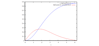
So I was thinking that when we use a s-curve to drive them, instead of choosing a symmetric one, where acceleration is is max in the middle of the acceleration section (as speed raises), I could try one where higher accelerations happen to lower speeds. However, in order to still keep the s-curve shape instead of a sawtooth, I would use the following expression: 1-e^(cos(t/2)-1)and it is shown in blue in the graph.
This will produce a s-curve shape, but modulated with the exponential behavior. Resulting signal will grow faster as the beginning (where more torque is available) and more slowly at the end (where faster speeds are reached and less torque is available).
A first test shows me that, for a bare motor, a faster move can be achieved, more reliably (no missed steps), using this pattern instead of a symmetric sinusoidal s-curve like s(t)=t-sin(t)
And what is even better is the above is achieved in a relatively shorter time: A 2000-step move would take 94 milliseconds with the exponential-sinusoidal s-curve reliably, while the same move using the symmetric sinusoidal s-curve would take 98 milliseconds but will fail (stall) 20% of the time.
For short movements, the difference may not be great, as no high speeds would be reached, but for high-speed motion, this pattern may be an interesting choice. As you can see, the acceleration is shown in red color in the graph above, and it peaks before 1/3 of the acceleration period.
The video shows how some of the CW movements stall while all the CCW complete without a problem. This is by no means a proof of suitability but just one sample case.


Comments