Testing another brushless motor
For my closed-loop control project I considered brushless motors to be a superior choice but the lack of affordable models in the marketplace let me down a bit.
I was able to find some cheap models on eBay but those were lacking of built-in encoder and my attempt to add them one was a bit of a mess: the optical disk and sensor require better alignment that my poor skills could provide, so it ended up not being reliable. On the other hand, most DIY can get a small part 3D printed and my previous tests with magnetic encoders encourage me to use them more often. So I took some time to tinker with a motor from Nidec and how I could get an encoder attached in a simple way.
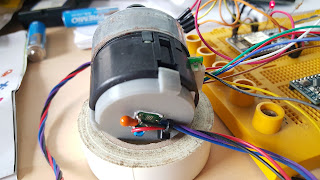
The end result is what you can see in the picture below, that just consist of a 3D printed part with three fingers that attach to the back of the motor's plastic cover notches.
You can see in the picture below the hole in the plastic box through which a small plastic part holds the magnet to the motor's shaft (a drop of superglue helped here). A small carrier board in the center of the plastic box keeps the sensor IC close to the shaft's magnet.
One of the unexpected benefits of using a brushless motor is that this one came with a built-in driver, so there is no need of additional electronics besides the loop controller. In this case I keep on using the ESP12E (or NodeMCU) that Mauro Manco kindly provided me a few weeks ago. But this time the part gave me some pain too. It turns out that PWM was not always giving the right output. it is is a software-based PWM and I was getting all the outputs for 8-bit PWM right except the value for 254 that turned out to be the same output as 0. That won't be a bit problem unless your motor's PWM input is inverted, like this motor I am using. Long story short, I had to lower PWM frequency to 10Khz to get it working ok.
As usual you can get the source code from my dcservo github. And the 3D printed cover.


Comments
I am happy to see your work and enjoy your posts.
Thanks
The Aliexpress link of the USB Oscilloscope you have posted is really a cheap one. Unfortunately , i already ordered :
http://www.aliexpress.com/snapshot/7304499644.html?orderId=72721263991724