Posts

Making sense of toolpaths

Image
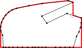
On my CAM project I am using the intersection of a part with a given plane to determine later the proper tool-path for three-axis machining. But sometimes, parts are such that the intersection line contains some concavity. So I detect whenever the tool cannot reach that line and create a suitable solution. In the picture the red line in the top removes any concavity as seen from Z-axis top, converting that polyline into another that might be machined from the top. It is interesting to note that one extra point needed to be created and appears marked with a dashed circle, though strictly speaking both bottom corners of the red line are new points too, but they are not over any of the original polyline space. A second problem appeared once I obtained not one polyline but several of them as a result of objects that contain holes or several domains with respect to the cutting plane as it is shown in the image below. In this other case, the different polylines need to ...

Getting the hang of it

Image
I have been using for a couple of weeks the web-based CAD system OnShape . I did this robot just as test to see how to use the different tools. I have been using OpenSCAD for quite some time and I was not very keen on using some fancy CAD systems like Inventor or Solid Works because I could not afford them but also because they would force me to use Windows, which I prefer not to. But even if AutoCAD can do OSX besides Windows, I do use Linux most of the time. So when I learned that there was a new game in town that was based I was first skeptical that a browser could to the job, but after some testing I am now a believer. And I love to be able to jump from a Linux workstation to a Mac to continue editing my designs. The free version of the service has certain limitations in the number of private projects you can have, storage and something else, but given the fact that can not only import but it exports to popular CAD formats like STEP or IGES it means your work is not locked ...

Rookie mistake with Makercam

Image
This morning I was in the lab of a digital manufacturing subject and I showed my students how they could do simple designs and turn them into a 2D manufacturing g-code without installing any software in their computers or tablets. I did show them the terrific OnShape.com online service that I have found very easy to learn and yet very powerful 3D design package. I performed a simple design. And later I showed how that could be exported as a DXF file and with the help of Inkscape it was written into a SVG file that Makercam.com online CAM software can handle. I selected metric units (though I would expected MM instead of CM but I guess it is ok for grid size purposes) and I proceeded to show the different machining operations available and how we will be cutting the thing. So minutes later we have g-code file ready to be loaded into our CNC router equipped with LinuxCNC software. After setting the whole thing up the process started and seemed to be working ok, though I had the i...

Getting more data from your PID controller

Image
Just knowing the steady-state error of your controller may not be enough for you to figure out how well your manual adjustment for your PID gains is working. In order to get a better picture of it you need to gather information while the loop is reacting to an input change.  However, just sending back information over the serial port while the loop is working may alter the very timing of things within the loop. So what I have done is to delay the monitoring information transfer till the loop reaches the steady state. That means actual position is recorded every millisecond and stored in an array so it is later transmitted once the motion is performed. Thanks to that I can see the system response quite nicely whether the response does have an overshoot or it is dampened properly enough. It really comes in handy when trying to set the P, I and D gains by hand.  The problem, however is that for doing this you need to have enough RAM memory and Arduino UNO is a bit shor...

One Arduino controlling two brushless DC motors

Image
After some changes I have been able to get it working reliably with two motors. But one of the changes I have made is to use a new type of motor that I reckon is better suited to the task. Instead of using brushed motors that are cheaper, I have found other brushless motors that have several advantages:  Being brushless, there is no other wear than the bearings They have built-in driving electronics, so they can be controlled with the Arduino digital outputs, which simplifies things and reduces interface costs.  Motors have built-in encoder disks, too, but the one they carry is just 100 lines per revolution (a bit poor, in my opinion) that can turn into 400 "steps" per revolution with the 4x decoding of the program. The lower number of lines per revolution puts less stress on the Arduino interrupt code, which may be one of the reasons it works ok now. I have moved all the encoder signals to pins that are monitored with the interrupt on pin change, and I have reserved...

Moshidraw: pain on every laser cut

Image
I have been using a [cheap] laser cutter machine. You can see which one on the following video.   Till now it kind of works but what is really annoying is the software you have to use to be able to cut and engrave. It is called Moshidraw and for reasons I cannot really understand it comes with a USB dongle for protection (it will not run without it).  Not in a million years I would like to copy such a program. This is what I have learned so far that causes trouble: If you DXF file contains curves, the operation will fail randomly (suddenly the cut will take an unexpected route and it will ruin your stock material). If you import a DXF and fail to select the part, the cut will did not work properly. If you have several parts in DXF, it may fail at any point (mostly when it is almost finished and all your stock material will be ruined). Best results and lower risk if you do multiple parts one at a time. There not seem to be a way to force inside cuts first, so some ...

3D Tool path generation

Image
I needed for a project to create a parallel finishing tool path similar what many CAM software does. There is nothing wrong with existing CAM software but what fun would be to just buy and use the software. The basic idea is that you can use a swipe plane across the mesh representing your volume and get the top part of each slice to be the tool path. A similar idea is used for 3D printing, but there the swipe plane is an horizontal one and object is built from the bottom up. The problem is that you cannot use the slice you just obtain from the mesh as milling bit (or extruded filament if 3D printing) has a non-null dimension. Because of that, just following the contour of the object will create a smaller result than the model. For 2.5D milling you can do a waterline finishing, doing flat passes on XY-plane. Thus a simple polygon offsetting operation can help you get the part dimensions right. But for 3D milling, the tool compensation becomes more difficult. The solution I opted...

Barcode listings with data

Image
A few weeks ago I mentioned a new tool I created for (allegedly) making my life easier when delivering marked exams to my students. Then I covered the process that happens after the exam. But one key element it was not mentioned is what it needs to do in advance. For my system I needed a set of labels. My prototype used Code-128 barcode that can handle ASCII code to encode each student email using barcode command-line program for Linux. The only problem with that was the lack of additional information being added to the label, such as the student name. Looking around I found a very handy tool by AVERY company, that helps you creating labels on-line for all their range of labels. What is even better is the tool will allow you to upload an excel file with data columns, like names and addresses to create a custom listing you designed and export it as PDF (they offer to print it for you to and deliver the labels to your office too). After some tweaks and, the most difficult part, di...

Maple Mini looking good

Image
This week I received a real bargain I wanted to test as a better candidate to be able to control several DC motors in closed loop. I have already tested the STM Nucleo 401 board and I get one 32 bit, signed, hardware encoder input on timer 2 and three more unsigned, 16-bit hardware encoder inputs on other timers. Unfortunately timer 5 was taken by the mbed library I was using. Nucleo is a solid platform and using the cloud IDE actually is not big deal for me. But now I have got a Maple Mini for $4  and I have to tell you I am totally sold. It is so much faster compared to an ATMega Arduino that I am positive it can do the work for controlling two DC motors closed-loop and most likely it can do four or more. The board can handle up to 16 external interrupts, enough for 8 encoders, and it can produce 12 PWM 16-bit resolution outputs (a far cry from 8 bit PWM from Arduino, though I am not sure that will have any impact on the system performance) plus plenty of memory (128K flash...

A better mousetrap so to speak

Image
Once in a while I need to mark exams. Exams do not tend to please students and marking exams is rarely a task anyone enjoys doing. But I cannot change that. What we do later is what I was trying to change for a while: For some years I have been using Scribd as a platform to make available the marked exams to my students. As I did not have a better tool, I started by doing the scan of the big pile of exams to later make it available as a document they can browse on the web (but not download). Making all the exams available to all the students is a liability that created me no trouble so far, but I can see privacy concerns plus fear of putting too much information in the hands of the students. To address the privacy concerns I did not made the document visible or public, but private so only those with the secret URL could browse it. On top of that, marked exams were kept available for a couple of weeks before being deleted. The idea of a student being able to review the whole marki...

Sometimes you get lucky, sometimes not

Image
I have wasted a fair amount of time today with a problem I solved the way I recommend to others: use a library. I needed to do a polygon offsetting in a program and I used what has worked for me in the past, the Java Topology Suite. I did my thing and it almost worked perfectly: However, I noticed a minor artifact once in a while. After some time I found that offset would sometimes did not work well as a weird line would appear crossing (line between to small circles) my beloved pumpkin instead or remaining on the outside (horizontal crossing was expected though). I as not trying to do a full offset but only of the part whose normals is between 0 and 180 degrees, as this project is related to 3d milling.  After a few hours of testing it all came down to a defect on the library (as far as I can tell) because with the same input data, but a smaller offset value, the operation was succesful as you can see below: I was unable to find a proper forum to ask other us...

Do more with less

Image
Following my previous post about using an Arduino for controlling a DC motor with an encoder in a closed-loop fashion some people have asked me if one Arduino per motor was not too expensive. Well, if you use an Arduino Pro Mini it can be less than $2 each. However, I do feel too that maybe we can do better. The main reason of my initial approach was that I had several signals that need to be handled fast-enough. On one hand, the quadrature encoder of the motor provides two pulsing signals that are used to know the current location of the motor shaft. This is accomplished by counting pulses, if not done fast enough, missed pulses will translate into position errors (and we are going closed-loop instead of using steppers to avoid exactly this same problem). On the other hand, the motor controller has to be able to receive pulses from the main controller (an Arduino Mega running Marlin) that control the motion of the motor. These pulses can be quite short and frequent (up to 40K...

Closed-loop DC motor to act as a stepper motor

Image
One of the things that I hate the most about 3D printing is that these machines are usually working in open loop and, sometimes, a tiny error happens that ruins a long print. Most 3D printers use one or more stepper motors to move each axis. Steppers are a good solution to the problem, they are easy to control and have lots of torque (compared to similar sized DC motors) but they may skip a step occasionally. The problem then is the print head is no longer where it is supposed to be but slightly off. From there on the print is misaligned and most likely will be useless. Any type of motor can be equipped with an encoder to check its location at any time. However that adds an additional cost to the equipment and requires extra software to handle this new information. One idea that has been mentioned many times in RepRap forums is that if steppers were replaced by DC motors with encoders that will allow the accurate position control that offer the steppers, the machines could be mad...

Loading TinyG2 in the Arduino DUE

Image
I have been intrigued for a while with TinyG controller and their S-shaped speed curves. It is an evolution from simpler trapezoidal speed patterns used by GRBL software and by most 3D printer firmwares out there too. However, TinyG (besides a South Korean music group) is not designed to work on a regular Arduino but over more powerful Atmel processors, the XMega series. While the software is open source, it does not help if you do not have the right processor. But lately I am giving a course where I have borrowed an Arduino DUE, which happens to be supported by TinyG project too. Uploading the code has been a bit of challenge, partly due to my attempt of using a USB cable with broken data wires (I did not know that as I use it for charging my cellphone). But even with a good cable, the upload process, at least using OSX was a bit of a challenge. It all comes down to a not entirely cooked script from their github . As I am not familiar with ARM development conventions, I see ...

Another one bitten by the bug

Image
While I have been doing electronics since I was a kid I never owned an oscilloscope before. At a local meeting of Arduino users a colleague mentioned me there was a very good offer of a four channel sampling oscilloscope. Not that I need to use it very often but I was curious enough to see how instruments have evolved lately I decided it was about time to have my own scope so it was kind of a birthday gift I bought to myself (if that makes any sense). First thing I have measured, just because it's right next to me is the the ringing of my 3D printer's hotend PID regulator output. It has been mentioned voltages can get pretty high over there in RAMPS boards and boy, that is true. At around a 50-volt spike is produced when the load is switched off. And the real value can only be appreciated if you freeze the sampled signal and expand widely the time axis, as the spike duration is below 1us. I guess total energy is so small the MOSFET is not really damaged (as it has been sitt...

VFD control with Arduino using RS485 link

Image
Variable Frequency Drives ( VFD ) allow the control of spindles so speed can accurately be controlled and a detailed acceleration profile for the spindle and reverse rotation can all be handled. In essence a VFD is an three phase inverter for three-phase AC motor. I am using a popular (I mean cheap) Chinese VFD and though the reference manual is not great, I could see there is a built-in RS-485 port. I usually control the start, stop and speed selection using the keyboard on the unit but I thought it will be more useful if I could control everything from the same Arduino is doing our CNC table control. Some cheap RS-485 off eBay and some lines of code later, I can start, stop and change the speed from an Arduino. What a cool thing to have! Some configuration of your VFD are needed before you can use it like that.  You need to set PD163=1 (I am using address 1 in the code). PD=164=1 (for setting serial to 9600bps) and PD165=0 (for using ASCII and 8N1 character for...

First steps with ESP8266 wifi module

Image
Some weeks ago it was mentioned in hackaday.com a new wifi module was available at a very tempting price (I paid $10 for two ESP8266  units shipped). It is a full SoC system which firmware can be updated. My main interest was to use it with Arduino projects and, perhaps, as a way to use my 3D printers wirelessly. The module offers, among other choices (I2C, SPI) a serial connection, running at 115200bps. Getting it to work has been a bit weird, as documentation was not very accurate and I was not paying much attention either. Care has to be taken with power supply as the unit is to be powered at 3.3V and using 5V will probably kill it. Likely it seems that I/O are 5V-tolerant (or so they seem till now). My initial setup has been to use an Arduino UNO as a power supply for the 3.3V and another 3V USB to Serial adapter with one FTDI chip. This way I was able to interact with the board using a serial terminal software (Coolterm). Unfortunately my initial setup was a no go. I...

The ever shrinking Arduino

Image
The las version of Arduino I bought is the micro. Around the size of the Arduino Pro Mini but featuring a processor that handles the USB port too and costing $7.50. As I bought mine from an Asian online seller off eBay I decided to give a try before providing feedback. Last week I have got trouble with two items I bought on Aliexpress: a set of Kossel linear rails that have rough spots along the rail and a set of hardened chromed smooth rods that are very smooth but bent too. In both cases they first impression was they were ok and I give them the heads up so they could get my money. Unfortunately, on closer inspection I discovered the problems mentioned above and I am still in the process of sorting it out with the sellers. This time I wanted to be quite sure everything worked as expected ... but it did not. I could happily upload new sketches once I selected the Arduino Micro as the target board. But I could not get Blink program to work. After checking Arduino docs about the Mi...

Stupidity-R-US

Today, after a long wait, I made my mind to shopping for a brand-new MacBook Air. I went to the Apple store in my city before the summer but I did not like what I was told: They will make me a nice discount for being a university professor but only if I was billed personally. I wanted the machine to be invoiced to my university that would slash the discount seriously. It did not matter that my university was a leading public university in the country. I left the shop shocked and empty handed. After checking with some colleagues it seems that is Apple's usual policy, though nobody was able to explain why. Anyway, after doing some taxes math I saw it was still more convenient for me to charge the bill to my personal expenses account I hold with my employer so I went for it. These is more or less my experience today at the Apple Store in Valencia. Apple rep1 (at the door): How can we help you today Sir? Me: I would like to buy a MacBook Air. Apple rep1: Do you have it reserved...

Reading binary STL files in Java

Image
I liked the source code from MaskedRetriever user on github and I assumed it would work ok. It seems it was an attempt to create a self-contained tool for 3D printing but somehow it was left at an early stage. But I liked the fact that source code was documented. My needs were to read STL files and to slice them. As usual you need to get familiar with the different classes involved but it took me not much to get it going. I stripped most of the classes as I was not interested on 3D printing nor on having a GUI for such a tool. However, as soon as I draw the output of the slice process I noticed something was wrong. While the proper slice looked smooth like the image below: What I was obtaining was a bit of a mess, though the general ideal was correct. As it was my first attempt I was not sure where the error might be. After a few tests I realized that the same code would work ok if STL file was ASCII-based but it will fail as above if a binary STL was used instead.  ...