Posts

Wifi DC motor controller?

Image
A few days ago I was talked on G+ by my friend Mauro Manco with an idea that was a bit weird at first: we all have heard about ESP8266 SoC that can bring Wifi happiness to out Arduino projects for a few dollars. What Mauro suggested is that this same unit might handle the servo code I have written for an Arduino. That was in part possible by the release of an SDK that allow us to program it the same way as a regular Arduino, so code-wise, programs are compatible. In a few attempts Mauro managed to get my code to compile happily for the ESP.  But he wanted me to try it out so he was as kind as sending me a NodeMCU board to my home so I could give it a try. It just arrived at noon and I could not resist to give it a try, as usual not without some minor problems. The first one was that the NodeMCU did not show up as a serial port in my Macbook. I tried installing the CH340 driver to no avail. After using a magnifying lenses I realised that the USB to serial adapter on my boa...

Presentations' clock

Image
I was recently invited by Pablo Murillo to give a talk at Zaragoza Maker Show  and I wanted [among other things] to present a hands-on project to the audience, outlining the process I followed to get it done. I was lucky my friend and fellow "Arduinist" Colin Dooley gave me away a 15-led addressable RGB stripe a while ago. Unfortunately, the Cylon effect (aka Lasrson scanner for those old enough) was already taken as one example from FastLED library, so I had to do something else. I have chosen the title "Beyond Blink" for my talk , so it would be nice to get something that, while blinking, performed a more useful work. So what I decided was to use the 15-led stripe as some sort of presentations clock, that will help the speaker to know the time elapsed, a new led lit each minute, while of them is blinking each second. But as many talks are longer than 15 minutes, I repeated the same pattern with changing colours for each next quarter. Red being the last colo...

Better accuracy from your encoder without more interrupts

Image
Since I published my DC motor control project on youmagine I have got some feedback from users with 2000 PPR (pulses per revolution) encoders or more where they end up having trouble above 3000 RPM. The reason is that the poor Arduino cannot process the interrupts fast enough and the system becomes unreliably. While optical encoders are available quite cheaply, some of the magnetic sensors from AMS are very competitive and offer very good accuracy (from 12 to 16 bits). One interesting model (due to its low price) is the AS5600, that provides a 12bit angle measurement for less than $2. Measurement data is read by means of an I2C serial bus and needs no interrupts. Hopefully those having trouble with interrupts can switch to this type of sensor, but model AS5600 is most likely a bad choice as it is intended to replace manual knobs in hi-fi equipment and it will not work at high RPMs (in fact the manufacturer does not provide the max RPM at all). But for position control applicati...

Getting dropcutter to work

Image
For my CAM project I was using a 3D offset of the parts to compensate for the tool diameter. But i have recently have incorporated a new feature so 3D assemblies of blocks can be represented in 3D. For the automatic assembly (courtesy of Carlos Sánchez) I cannot use the offset surfaces but I have to use the original meshes. One way of machining a 3D mesh is dropcutter algorithm, that in a nutshell works by modeling the milling bit and setting the z-depth at each XY location so the model is barely touched by the tool. As meshes are made of triangles, each feature of them is tested for contact: edges, facets and vertices. The feature with the highest z-depth value will set it for that particular location. I have found a lot of insight and useful information in Anders Wallin blog . Though my initial approach was to adapt his monocam's C# code to Java, I ended up with a buggy result. Anders released later a C++ library, opencamlib, that is most likely a much improved version, ...

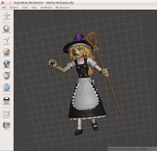
Native 64bit Meshmixer version

Image
I have just noticed there is a new version of Autodesk's Meshmixer software available for Linux but this time is no longer running over wine but it is compiled to run in Ubuntu 14.04 64bit. And the first tests suggest it works reliably (only crashed once when searching on the online 123D library). It is a great program and it is free to use so I find myself using it from time to time. There are quite interesting but unexpected uses . It is been a while since I last checked, so do not bash me if this is not new news for you, I now it was released first around March 2015, but I am a bit slow :-)

Simple schematics on the web

Image
I wanted to create a simple schematic for my students. I could use an electronic CAD system but I needed something simple and quick. I look it up on the Internet and I have found a few choices. The first one was from Digi-Key and it worked nicely for my job as shown below (you may want to click on the image to get it to readable size). It was documenting the circuit of a simple electrostimulator to be used with an Arduino for creating some pain. One of my students wanted to build an Arts installation will cause him physical pain and this one fits the bill. For the rest of the people, the usual disclaimer is in place: use it at your own risk.

Banging my head with Java line separator

Image
One of the most unpleasant experiences with computers is having to solve a problem you already fixed when you realize the old solution is no longer working for reasons unknown. The problem this morning was quite silly, actually. One piece of code created a text file. I did not care much about the way newlines were represented but when  I sent the file to to a colleague that uses Windows he complain notepad was making a mess out of it. It was clear notepad was doing this because my file, created on a unix system, did not honor Windows end of line convention of CR plus LF characters (0x0d + 0x0a). I have solved that in the past just changing the System property called line.separator. You could do that with System.setProperty("line.separator","\r\n") but apparently not anymore. Of course, no error message or exception is raised, so you are left alone, in the dark, trying to figure out what is wrong and why what worked before does not work now. I could not make m...

The right interface

Image
When I was a teenager I was an avid reader of electronics magazines. What was available at home at first and later what I could afford. I remember that my favorite ones was Elektor magazine, that grew from a German-only magazine to be distributed to other languages and countries, mine included. They have this great summer edition that included over a hundred different small circuits. Over the years I have almost stopped buying magazines (not because they are bad but because they use shelf space and I have not much time to read them). The last paper copies I bought were from Circuit Cellar Ink, but these same guys decided that a digital edition will ease their business, and for those abroad it will be be much cheaper. Selling bits is a good idea that seems to be making Google and many others much good. I even wrote several articles for Circuit Cellar magazine about different projects I made. A few years ago I learned that Circuit Cellar Ink was acquired by a European group that hand...

First impressions on bq's Hephestos 2

Image
I was asked to be a beta-tester of this new machine sold in kit form by Spanish firm bq .  It's a bit hard to keep the experience to myself while the testing was taking place. I won't say it is great and rosy but their approach was a bold one and I think it stands out of the crowd. So what is it? Hephestos 2 is a 3D printer kit to be assembled by the user. While it might find its routes in Josef Prusa iteration 3 model, this time it is just a faded image. That was entirely the case with the former Hephestos that shared most of Prusa i3 features with a few of exceptions: no heated bed, a couple of cable chains and a very well engineered extruder/hotend combo. But the Hephestos 2 breaks with the Reprap tradition and includes no printed parts and a body made of powder colored folded metal parts. Only Y-axis uses 8mm diameter smooth rods and linear bearings but Z and X-axis use miniature Hiwin linear rails for extra accuracy. A new electronics board integrates an ATmega 2560 ...

More on DC motor "stepper emulation"

Image
The code I developed a while ago for using a DC motor (or a BLDC) to replace a stepper has got quite an interest among youmagine users. Over time I realized that some of the quick and dirty things I did were preventing the easy exploration of system parameters for users. Using different PID parameters required a recompile and of the sketch. I recently received a Printrbot Simple from Brook Drum with the goal of testing with that printer my closed-loop solution.  As usual, simple things (in theory) become tougher that initially expected. First of all, it took forever for the printer to clear through customs and while Printrbot provided and shipped the printer for free, the taxman wanted its cut no matter what, and it took more than too weeks for that to be worked out. We settled on the Simple because it had more room for the motors to fit in though carriages might be heavier than the Play. At the time I did not know the CAD of both models was available on Youmagine, so I...

How to do a CNC milling farm.

Image
One of my current projects requires to run two, maybe more in the near future, DIY CNC machines. Machine controller is USB-based and a PC could be used to send g-code to machine controller. However, we have tried a different approach that proved successful: using a cheap tablet instead of a PC. It all started by testing the excellent program GCodePrintr by Mathias Dietz. This software is designed so people can use a 3D printer directly from a tablet. You can stream a g-code file for printing to the printer plus you can do all the usual manual functions of moving the axis around. Besides, a graphical simulation of the print is represented on the display. And in the few tests I did, printing speed did not seemed to be compromised because the lower tablet performance (compared to a PC). However, uploading a file from Dropbox or using some FTP app for sending g-code files to the tablet was not very convenient as required user time spent at the tablet. But one feature of GCodePrintr ...

Basic 2D CNC milling workflow

Image
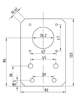
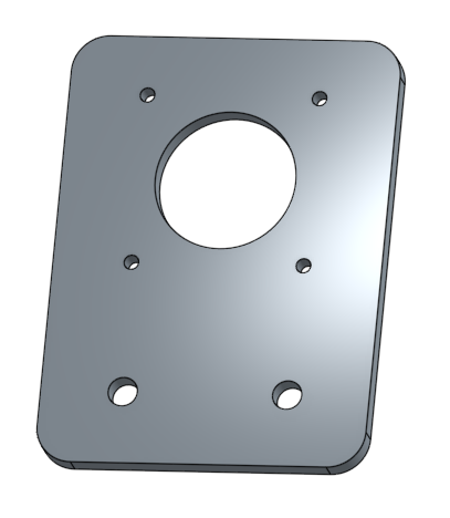
I needed for a project some metal holder plates for nema 23 motors. As I have in the lab a Chinese 6040Z CNC router I thought it will be an easy thing to do. Oh boy, how wrong I was. They project was a simple plate (very easy to sketch using OnShape ). Once it was sketched a 3D part could be created by simply extruding it, which may come in handy if some drawing assembly needs to be done for documentation purposes. However, for 2D projects a 3D model of the part is not really needed for the process of creating 2D machining code. There are different solutions out there that are free, but one that I like because it is very simple to use and it is on-line is makercam.com but for that you will need an SVG file instead of the DXF that OnShape can easily produce.  I usually use Inkscape software for converting to and from SVG and DXF. I did so in this case and it worked as expected. So, once I have got the SVG file I can feed Makercam.com I need not to forget to c...

Using a tablet to control a CNC machine

Image
I do have some CNC routers using Arduino Mega and Marlin as pulse generators and g-code interpreters. Usually they are connected to a computer for selecting and streaming g-code files to the machine. Lately I was testing a new machine and I found an old Android tablet laying around, so I wondered if it could be used for the task of controlling the machine. I am aware of programs like Octoprint that can do exactly that using a RaspberryPi and I have seen it does a great job. However, unless some more hardware is added to the mix, no display or user input is possible. But a tablet already has the display and touch screen that can be used for that purpose, plus Wifi and Bluetooth for wireless communication. What was needed was a USB connection but for that a cheap OTG USB cable was all that I needed. Well, once the hardware side is solved, you need some software and after checking and testing different options I ended up with GcodePrintr . A software that is designed for controlling ...

Closed-loop motor control for 3D printers

Image
It is been a while since I brought this topic in my blog. I recently bumped into this thread on element14 about the same topic too. I was naive enough to assume that what shows up on eBay or Aliexpress can be available for quite a long time. It appears that some the units just pop up for a while to never be seen again. That has been the case with some of the motors I have been doing tests with. Since I realized that steppers could in fact be replaced in our 3D printers by a closed-loop DC motor I have been tinkering. One of the key ideas was to find a steady supply of motors that would enable anyone interested into building the same contraption. And while the brushed motors I used worked as expected and were cheap enough, they seemed a bit too weak (not enough torque for higher accelerations) and I was quite worried about how long they will last. On one hand there is the argument that if inket printers replaced steppers by closed-loop brushed DC motors, we could do the same and ...

Minimizing tool air-time

Image
For a CAM software I wrote, intended for milling foam sheets, I needed a way to improve machining time, so once the feed rates are raised to the limit, the next step is to reduce any wasted time. On an initial approach, our tool was finishing parts one after the other, so there was a bit of the tool going back and forth within the same part. While it may seem the whole problem is like a big TSP (travelling salesman problem) and the way to optimize the used time is to connect all the dots with the shortest possible path, it is not exactly so. On a milling operation, the tool path has been carefully calculated so it will remove the proper amount of material by following a certain path. Changing such a path will alter the finish of the part and we do not want to go there. So what we really have is something like two different sets of movements, one that corresponds to the actual cutting operations and a second one that moves the tool over the air to start a new cutting operation....

Importing OpenSCAD designs into Onshape

Image
After using Onshape CAD software for a while I am really fond of it. So one natural thing to do, specially once they have released the Instructor's kit is to start using it in the classroom too. But one thing I was not so sure how to do was to use old designs I made using OpenSCAD. It does not mean I am completely quitting using OpenSCAD but suddenly I can see I can do assemblies in Onshape that will look quite nice for showing and documentation purposes if only I could easily import from OpenSCAD. I am glad to report that the route OpenSCAD --> FreeCAD --> Onshape worked brilliantly. Even more when a few tricks were applied. While some people suggest to import CSG files from OpenSCAD to FreeCAD, I have had more success by directly importing SCAD files into FreeCAD. One trick that worked well for me was to get rid of $fn references, so now circles become real circles (or cylinders) in FreeCAD. If a part keeps some $fn references then your cylinders or circles wi...

Decoding barcodes from scanned pages

Image
A while ago I created a tool that would send the marked exams to my students by email. I used adhesive stickers with a QR barcode they put in the first exam page once they are done. The system kind of works and even some colleagues have started using it too. The problem is that once we have the pile of marked exams scanned as a single PDF file, barcodes need to be read reliably. It is not that the scanned images are bad. I usually scanned it at 200dpi grayscale. The problem is that even if I set the black to the strongest setting is not good enough for ZXing library to decode it properly. And of course if the code is not decoded properly all the system goes under. For a while I have been cranking up the black color using Imagemagick command line tool and when that was not good enough I realized that blurring the document would also helped. While I get that working, the exam itself became not so nice to read after that. Anyway, after a bit more of testing I realized that ...

Making sense of toolpaths

Image
On my CAM project I am using the intersection of a part with a given plane to determine later the proper tool-path for three-axis machining. But sometimes, parts are such that the intersection line contains some concavity. So I detect whenever the tool cannot reach that line and create a suitable solution. In the picture the red line in the top removes any concavity as seen from Z-axis top, converting that polyline into another that might be machined from the top. It is interesting to note that one extra point needed to be created and appears marked with a dashed circle, though strictly speaking both bottom corners of the red line are new points too, but they are not over any of the original polyline space. A second problem appeared once I obtained not one polyline but several of them as a result of objects that contain holes or several domains with respect to the cutting plane as it is shown in the image below. In this other case, the different polylines need to ...

Getting the hang of it

Image
I have been using for a couple of weeks the web-based CAD system OnShape . I did this robot just as test to see how to use the different tools. I have been using OpenSCAD for quite some time and I was not very keen on using some fancy CAD systems like Inventor or Solid Works because I could not afford them but also because they would force me to use Windows, which I prefer not to. But even if AutoCAD can do OSX besides Windows, I do use Linux most of the time. So when I learned that there was a new game in town that was based I was first skeptical that a browser could to the job, but after some testing I am now a believer. And I love to be able to jump from a Linux workstation to a Mac to continue editing my designs. The free version of the service has certain limitations in the number of private projects you can have, storage and something else, but given the fact that can not only import but it exports to popular CAD formats like STEP or IGES it means your work is not locked ...

Rookie mistake with Makercam

Image
This morning I was in the lab of a digital manufacturing subject and I showed my students how they could do simple designs and turn them into a 2D manufacturing g-code without installing any software in their computers or tablets. I did show them the terrific OnShape.com online service that I have found very easy to learn and yet very powerful 3D design package. I performed a simple design. And later I showed how that could be exported as a DXF file and with the help of Inkscape it was written into a SVG file that Makercam.com online CAM software can handle. I selected metric units (though I would expected MM instead of CM but I guess it is ok for grid size purposes) and I proceeded to show the different machining operations available and how we will be cutting the thing. So minutes later we have g-code file ready to be loaded into our CNC router equipped with LinuxCNC software. After setting the whole thing up the process started and seemed to be working ok, though I had the i...